By Grant Knowles
To assist you with assembly of the Silver Plume Bakery, I have have produced the following set of instructions. These are based on the Kit Instructions with liberal amounts of my experience in assembling structures injected and what I did for this particular kit.
I have made reference to steps in the original kit instructions as follows: “(ref Assembly 1). This is to help you correlate the two sets of instructions together. For the most part we are following the Kit Instructions sequence with occasional digressions where it makes assembly easier.
 At first it is always confusing when it comes time to sort out the many pieces in the kit. To help you along with this, I have added part numbers to the layout plan and then referenced these in the instructions. Click on this image to obtain a printable version of this plan.
One final trick. When you complete a step, be sure to cross it off so that you know you have completed it.
Step 1
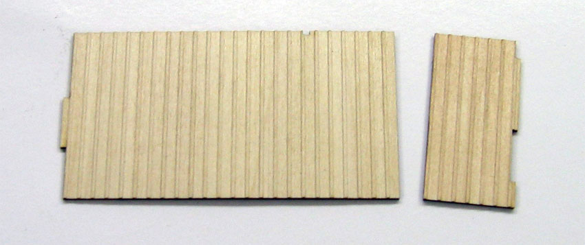
Glue the two floor panels together (F1 & F2), see photos below. After the glue has dried, sand the edges flat by placing a fine grit sheet of sand paper down on a flat surface and running the floor assembly back & forth on each edge. Do this only until the edge is smooth. (ref Assembly 1). We’ll glue the third (door step – F3) piece in place towards the end of the process.

Here are the two floor panels. The top one (on the left) is glued on top of the right piece.

I clamped by floor panel over night between two flat pieces of plywood.
Step 2
Locate all the wall panels and determine how “distressed” you want them to be. Now is the time to scratch up the boards, add nails holes, cracks etc. Do this to all the exterior facing surfaces (pieces S1 – 10). You may wish to refer to our clinic on Texturing The Wall Panels for ideas on this topic.
Step 3
Paint all the wall pieces from Step 2 along with all the trim, window & door pieces. Don’t worry if you miss a few, you can always paint these overlooked pieces later.
Mike Hamer’s shares some of his painting trade secrets on the Model Painting web page.
Step 4
In the HO scale kit, the left wall is comprised of two pieces of board & batten sheet stock (S2).
Locate the two pieces and dry fit the pieces together. Note the larger piece has a notch in the upper edge. I like to use a flat surface that will accept sewing pins when assembling flat panels. This one is a ceiling tile with some cardboard glued on top. Lay out the two pieces on this flat surface and use pins to hold them in place. Run a small bead of glue along the adjoining edge (yellow carpenters glue is my favourite for wood to wood joints) then hold them together with pins. I also placed a weight on top to hold the panel flat while the glue dries.
Note the notch on the upper edge of the right piece.

The two panels are butt glued together. The pins and lead weight hold everything in alignment while the glue dries.
Step 5
Assemble the Right Hand wall (ref. Assembly 2). This wall is made up of three panel pieces that interlock together. The trick here is to ensure they are interlocked together correctly and are flat.
Locate the three pieces (S1, S2 & S6). Lay these on a flat surface that will accept sewing pins. Mount a straight piece of wood on the board so that you can align the bottom edges of the wall pieces against this. Apply a small dab of yellow glue on the matting surfaces and hold the wall pieces in place with the sewing pins. You may need to lay some weights on top of the wall panels to hold them flat. Make sure you have aligned the three pieces together as per the illustration in Figure 1 in the kit instructions. Let this glue dry overnight.
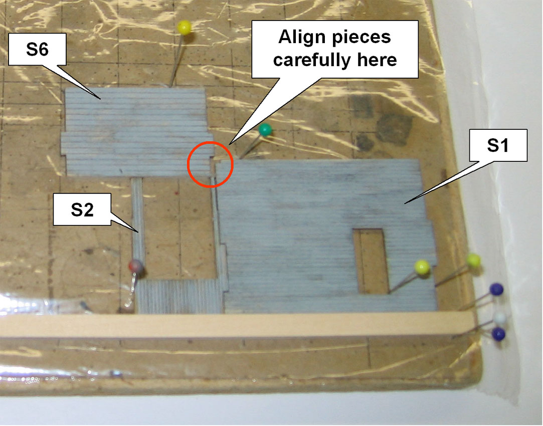
The plastic wrap prevents the glue from sticking to the board.
Step 6
Assemble the front wall in the same way as you did the side wall. You will need pieces S3 & S7. Note the left hand edge of the upper panel is to be lined up with the end of the interlocking tab!
Step 7
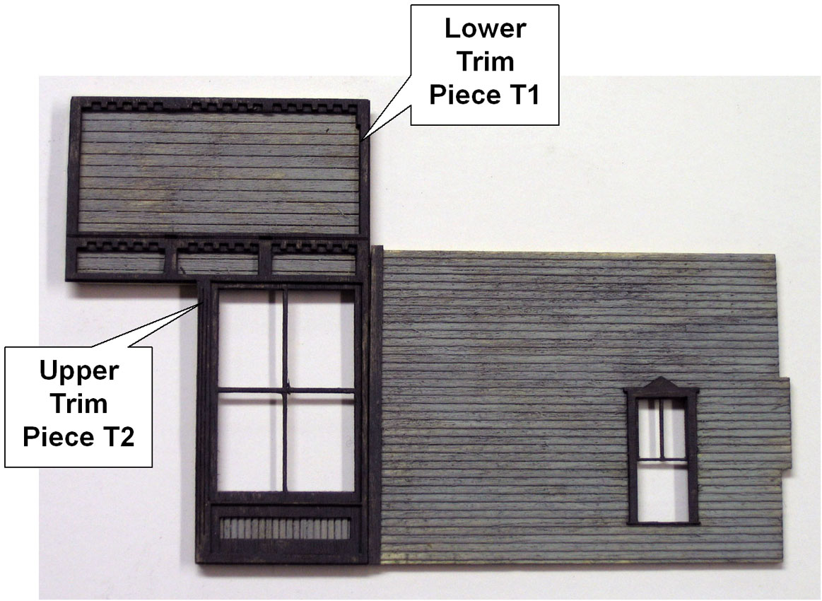
Apply the overlay trim pieces to the wall assemblies. Start with the Right Hand wall. Locate trim piece T1. Before you peel the backing off, test fit the piece on top of the wall to ensure if fits and you understand how it is to be located. Now pull the backing off to expose the self adhesive and place it gently on the wall while aligning all the edges. When you are satisfied you have it located correctly, gently push down on the trim piece to set the adhesive (Ref. Assembly 4). Note the tabs will be covered up by the trim pieces.
Step 8
Locate trim piece T2. This is a rather ornate piece so be careful when you cut it out of the fret. This piece installs on top of the Right Hand wall assembly. Once again, verify it’s fit before you peel and stick it in place (Ref. Assembly 4).
Step 9
 It is now time to follow the same sequence to install the trim on the front wall. Locate and install the lower trim piece T3 and the upper ornate trim piece T4. Remember to ensure all the pieces line up (Ref. Assembly 4). Note the trim pieces overhang the top right edge of the horizontal siding slightly. This is intentional as it will then cover the trim on the right side when the walls are assembled.
Step 10
 On the Right Hand Wall, glue a strip of 1×4 just to the right side of the display window trim. This will hide the join between the two lower wall panels. (Ref. Assembly 6).