Introduction
Our final Arduino project for this season will be directed towards building & delivering a model railroad related system that everyone will find useful. Of course, the core objective here is to increase our knowledge and comfort level with Arduinos through leveraging what we have learned over the past few months regarding Arduinos and associated programming. Through this exercise we’ll add a few more functional capabilities to our portfolio.
After careful consideration and participant endorsement, we settled on creating a Sound System that can be deployed on our layouts adding further (audio) animation to our empires.
This project will:
- Introduce the Nano microprocessor.
- We will learn how to program and manage a Nano
- Introduce the DF Player and learn how to control it
- Explore trigger scenarios to initiate the playing of sounds.
- Learn how to locate sound files, prepare and load them onto a SD card.
Project Approach
To acquaint myself to the scope of work required to design, build & program an Arduino based Sound System, I reviewed various Arduino Sound related articles and watched several YouTube tutorials. All have relevant information, but I could not find one that was all inclusive guiding the reader through the full end-to-end process. So, what I have assembled here is approach I settled on by combining the best material from these various sources. As with our Warehouse Door project, we are following a phased approach which will enable us to build/learn in logical steps ultimately resulting in a Sound System that is ready for the layout, etc.
The proposed phases are:
- Preparation Activities
- Preliminary Information
- Download & install Libraries.
- Sourcing sound files
- Load sound files onto Mini SD card
- Configuration 1 – DF Player alone
- Bread board DF Player, use buttons to control the Player
- Connect a speaker
- Play sound files
- Configuration 2 – Arduino
- Bread board the DF Player with the Arduino
- Use push buttons as input devices to the Arduino
- Create sketch & up load
- Play sound files
- Introduce Triggers
- Identify trigger scenarios
- Motion detector
- Time based
- Random
- Managing Sounds Files
- file formats
- Editing Applications
Phase 1 – Preparation Activities
Step 1 – Preliminary Information
Before we jump into the project, we should acquaint ourselves with the scope and material.
Here is a good short overview of the Arduino with DF Player system.
Arduino-Based MP3 Player via DFPlayer Mini Module (YouTube Video)
Further information regarding the DF Player can be found at this site (Dfrobot DF Player Wiki Details):
Dfrobot DF Player Wiki Details
Includes device overview, schematics and sample sketch.
Step 2 – Download and Install Libraries
We will be utilizing the DF Player to host / play our sound files.
To interface with this device, we will require two Arduino libraries:
- SoftwareSerial – (SoftwareSerial.h) – required for the Arduino/Nano to communicate with the DF Player. This library currently exists in your IDE library list so you do not need to source this one.
- DFRobotDFPlayerMini.h – This is a new library which contains all the functions for interfacing with the DF Player audio module.
You can download the DFPlayer software library by following this link
- Click on link and save the zip file in a local folder on your computer (I chose the desk top)
- Open the Arduino IDE application
- Go to: Sketch / Include Library / Open.ZIP Library. Locate the ZIP file and click OK.
The IDE will place the new DFPayer Library under the Contributed Libraries section
This completes installing the DF Player related libraries.
Step 3 – Sourcing Sound Files
Fortunately for us, there are many sources on the web that provide sound files for free.
Here is what I initially found in YouTube on the topic, I have not checked them all out yet.
- Best Free Sound Effects // Top 5 Online Sound FX Libraries
Top 5 Online Sound FX Libraries (YouTube Video)
Sites they recommend include: - freesound.org You are required to set up an account in order to download files (no cost)
- Soundbible.com They require attribution
- Youtube audio library
- 99sounds.org
- GDC Game Audio BundlesThis is a gamers library site – this is likely of little use to us
- The Four Best Sites to Search for Free Sound Effects #freesoundeffects
Four Best Sites to Search (YouTube Video) - How to Find & Use AMAZING Sound Effects for Your Videos (No Copyright Strikes!)
AMAZING Sound Effects (YouTube Video)
At this time I focused on MP3 format sound files. The DF Player supports a number of file formats to which we’ll explore others at a later time.
When you have located the desired sound files, download these to a folder on your PC.
Step 4 – Load sound files onto Mini SD card
We’re now ready to load the sound files onto the SD Card.
Prepare SD card.
- Format the SD card with the FAT or FAT32 file system. Note, check the SD Card Properties first as it is likely already in one of these formats, if so, you do not need to format it.
- Create two special folders using the names mp3 and advert.
- Additionally, you can create 99 more folders using the names 01 to 99. These 99 folder names must be exactly two digits long zero padded.
- Copy one or more MP3 audio files into the two special folders, mp3 and advert, and to the 01 folder. You need to rename the audio files using the following format:
- The filenames for the MP3 files that you put inside the two special folders, mp3 and advert, must start with four digits zero padded, and then optionally a long filename after. You can have up to 255 files inside these folders. For example, “0001 Welcome message.mp3”
- The filenames for the MP3 files that you put inside the 01 to 99 folders must start with three digits zero padded, and then optionally a long filename after. You can have up to 255 files inside these folders. For example, “001 Jack and Jill.mp3”
- You should now have three folders on your SD Card according to:
- mp3 files named 0001_xxx.mp3 in the mp3 folder.
- mp3 files named 001_xxx.mp3 in the 01 folder.
- mp3 files named 0001_xxx.mp3 in the advert folder.
- Eject the SD Card from your PC following the Storage Medium Ejection procedure.
NOTE: The order you copy the mp3 into micro SD card will affect the order mp3 played, which means play(1) function will play the first mp3 copied into micro SD card.
Phase 2 – Configuration 1 – DF Player Alone
The first phase will involve playing a MP3 file on the DF Player. Since the DF Player is a new device for us, we will first focus on understanding it and how it functions without utilizing the Arduino.

Figure 1: DF Player with power, speaker and buttons connected.
| DF Player Pin | Description |
|---|---|
| GND | |
| VCC 3.3 or 5 V | |
| SPK_1 Speaker | |
| SPK_2 Speaker | |
| IO_1 | |
| IO_2 |

Figure 2: DF Player pin outs.
Insert the DF Player board on your bread board.
I used the auxiliary power board that came with our Starter Kit to power the bread board. Pin 1 VCC is connected to plus 3.3 or 5 volts. Either ground pin 7 or 10 is connected to the negative power rail.
The speaker is connected to pins 6 and 8.
You can add momentary contact push buttons to pins 9 and 11 or do like I did and just use a loose wire lead on each (these are the blue & white wires in the photo). We will be connecting to some of the other pins later on.

Turn on the power, you should hear a tick – tick sound from the speaker indicating it’s working.
Turn the power off and insert the mini SD card that you had prepared earlier. Make sure it’s right side up and fully inserted.

Here the mini SD Card is partially inserted.

Here the mini SD Card is fully inserted.
Turn the power on.
Touch the Pin 11 wire to ground thus increasing the speaker volume. Tap the Pin 9 wire to ground to play the first MP3 file. Notice the red LED on the DF Player is lit while the file is being played. Once the file has played, the light will turn off.
Tapping pins 9 & 11 to ground will move up/down your MP3 files you have on your SD card. I had saved three so that I could experiment with the functionality.
Holding the pins to ground will increase/decrease the volume.
I had better luck running on the 5v rail than the 3.3v but I suspect I was encountering poor pin connections in my bread board.
Phase 3 – Configuration 2 – DF Player with Arduino
Step 1 – Hardware Set Up
The next step in our Arduino – DF Player project is to connect the DF Player to the Arduino UNO which in turn will control the DF Player’s functions.
Through my search on the internet I found a number of sites and YouTube videos that that provided valuable information along with sample sketches that met our needs. But there was an issue lurking in the shadows here!
My first wiring attempt was based on this diagram ( https://wiki.dfrobot.com/DFPlayer_Mini_SKU_DFR0299#Connection_Diagram ), which was common to nearly all the sources I found. The connections are:
| Arduino Pin # | Description | DF Player Pin # | Description |
|---|---|---|---|
| Tx to DF Player | Rx UART Serial Input | ||
| Rx from DF Player | Tx UART Serial Output |
As you will notice, there is a 1 K ohm resister on the Rx lead to the Arduino.
When I ran the sketch, the Arduino failed to connect to the DF Player. Further investigation of the problem through examining the hardware and software, I confirmed all was in alignment with the “on line” information then I stumbled across this YouTube video – DF Player Mini MP3 Module Testing that demystified my problem. As it turns out, the DF Player Rx input (pin 2) is set up to accept a maximum of a 3.3 v input signal, unfortunately the Arduino output is at 5 volts, thus I had initially over powered the RX input lead on the DF Player thus damaging the input circuitry. The correct wiring for this pin is to create a voltage divider with a pair of resistors thus guaranteeing the Arduino does not over power the input pin. Thus the correct wiring between the Arduino and DF Player is;
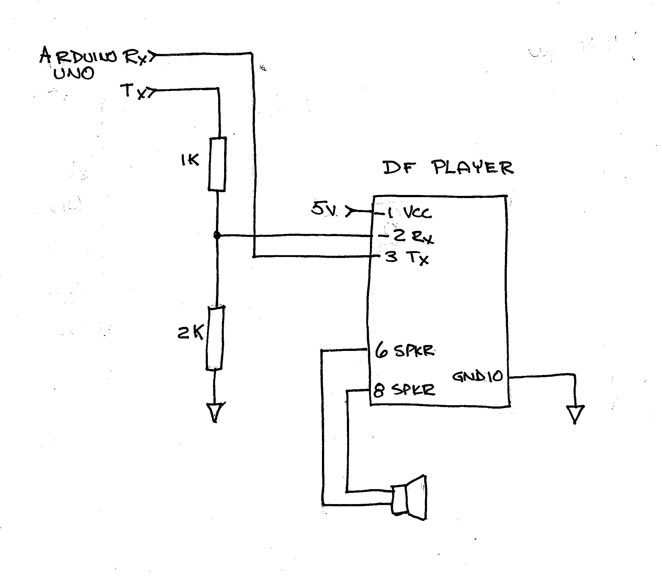
Figure 3: Correct Arduino – DF Player connections
Fortunately, I had a spare DF Player on hand as the first one is now useless.
I also used the +5V and GND from the Arduino to power the DF Player module.
The speaker, as before, is connected to pins 6 & 8 of the DF Player.
This completes the physical set of the components.
Step 2 – Software
For my initial test, I leveraged the sketch found on the DFRobot site as it contained a number of nice features (which aided in my initial trouble shooting) https://wiki.dfrobot.com/DFPlayer_Mini_SKU_DFR0299#Connection_Diagram
- Changed the serial baud rate for the DF Player,
- Increased the sound volume to 20, and
- Lengthened the playing time for the sounds to 5 seconds.
Here is the link to my revised sketch – DF_Player_-_Arduino_-_20 (ino file)
Please note that three libraries are required:
- #include “Arduino.h”
- #include “SoftwareSerial.h”
- #include “DFRobotDFPlayerMini.h”
We have used the first two early on with the Elegoo Lessons so these will already be in your library collection. The DFRobotDFPlayerMini.h is the new one you had added to your library collection in the first step of this project.
Load the sketch into your IDE and save it on your computer. Note this will be our initial/first sketch for the DF Player, we will evolve this sketch so chose a naming/numbering convention for each new version we develop.
Load the sketch into your Arduino. The code will start on it’s own and should commence playing the sound files on your SD Card. Since I have three MP3 files saved, the sketch continuously cycled through all three playing them in sequence.
Phase 3 – Configuration 3 – DF Player / Arduino With Push Buttons
Step 1 – Hardware Set Up
The next step in our Arduino – DF Player project is to introduce some push buttons that will enable using the Arduino to control the DF Player’s functions. We will expand upon the system set up / sketch used in the previous exercise.
The five buttons we will add are:
- Next – plays next saved sound file
- Previous – plays the previous saved sound file
- Pause – will cause the DF Player to pause playing the current sound file
- Volume up – increases the speaker volume
- Volume down – decreases the speaker volume
We will also add an LED to indicate when the “paused” function has been enabled.
Here is the circuit schematic.

Figure 4: Arduino – DF Player with Buttons Schematic
For the buttons, each of the UNO Inputs (pins 2 to 6) are connected to ground through a 10K resistor. A push button is also connected to the UNO pin and the other side of the button is connected to the + 5v rail. Thus, the input to the UNO is at Ground level potential until the button is pressed which then brings up the input voltage level to 5v which is viewed as a “high” by the code.
Here is a photo of my completed set up.

Figure 5: Arduino – DF Player with Buttons
Step 2 – Software
The sketch for this configuration is based on the previous exercise sketch where we have added the functions to monitor the five push buttons, to send the corresponding command to the DF Player and to turn on the Pause LED at the appropriate time.
Here is the link to my updated sketch – DF_Player_Arduino_Buttons_-_20 (ino file)
And here is a PDF document with the altered code highlighted in red font for your reference. – DFPlayer Arduino with Buttons (PDF file)
Load the sketch into your IDE and save it on your computer.
Load the sketch into your Arduino. The code will start on it’s own and should commence playing the sound files on your SD Card. Exercise the buttons to move through your sound files and to changes the sound volume. The way the code is written, it will play the current sound file to the end then will stop there until you press a button to play the next or previous sound file.
Note, you may need to add your auxiliary power source ( a 9v battery in my example) if your computer’s port does not have the current capacity to power the speaker at high volume.
Phase 4 – Configuration 1 – DF Player / Nano With Push Buttons
The next step in this exercise is to transition our solution to the Nano microcontroller board from the UNO device.
Step 1 – Hardware Set Up
Though the Nano device is about half the size of the UNO, it has the same number/type of interface pins plus two additional data pins. It is based on the same processor chip (Atmega328) and has the same flash memory capacity. The key difference is it does not have a separate power input socket and uses a mini USB connector.
The Nano microcontroller does not have sockets for external connections, instead it will need to be installed on PCB board that contains terminating capabilities be it solder pads, sockets, screw terminal blocks, etc.
For this exercise, we’ll insert the Nano onto our bread board to facilitate connecting to the microcontroller pins.

Figure 6: Pin labels for the Arduino UNO
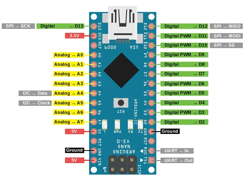
Figure 7: Pin labels for the Arduino Nano
Install the Nano onto the bread board.
Install the Elegoo Power Board onto the bread board.
Connect the Nano VIN and Gnd to the bread board rails (+5v & Gnd).
As was done with the previous UNO exercise, wire the push buttons / resistors to pins 2 thru 6, the LED on pin 9 and connect the DF Player Tx & Rx to pins 10 & 11 on the Nano. Refer to the schematic in Figure 4.
Connect the DF Player Power & Gnd terminals to the bread board rails.
Step 2 – Software
We’ll be using the sketch from the previous exercise but the first thing we need to do is reconfigure the IDE to interface with the Nano.
Open up your IDE, then under the TOOLS menu, configure the following:
- TOOLS / BOARD “Arduino Uno”
• Change this to “Arduino Nano”

- TOOLS / Processor “ATmega328P”
• Change this to: “ATmega328P (Old boot loader)”

- TOOLS / Port “COM6”
• Make sure this is your active port, most likely it has not changed from what was set up for the UNO. My system happens to be using COM6, yours may be different.


Of course, when you go back to the UNO, you’ll have to return these settings to their original values.
Open your sketch from the previous exercise with the IDE then select the compile/load button.
The sketch should load into the Nano and the Nano will commence functioning.
Exercise the push buttons, they should behave exactly the same as with the UNO.